Longtime readers of our blog will know that one (or two?) of the earliest
projects we shared in a previous blog post are passports
and door-opener. If you’ve missed it, you should definitely go and check out
how they work, but today we’ll be focusing on door-opener.
We spent the past year designing, building, and deploying the new door-opener
that would solve some of the problems that started to manifest with the
original, while adding new quality-of-life improvements for the organizers
setting up Hack Night.
I shared parts of how door-opener-v2 came together
during my BENTO talk, but because the goal of BENTO was to
condense everything down to within 15 minutes, a lot of material was left on
the cutting room floor. So here’s a more detailed look at how door-opener-v2
came together, starting all the way back at the beginning.
Entropy, and the cruel passage of time
door-opener was initially built by Hazel Roeder, and her design had been
working flawlessly, up until Fall 2025. Unfortunately, while the design itself
would’ve lasted a lot longer, the materials for the suction cups, as well as
some of the internal components like the fan bearings, were starting to wear out.
We decided to prioritize a more permanent solution for this problem when people reported that they couldn’t get to Hack Night anymore, because the modules kept losing their grip and falling off of the surfaces.
So on September 2025, a new channel on our Discord was created, and I’ll try my best to summarize the important milestones we hit up to the present.
Idea-sharing and trimming
We first had to decide what the second revision of the project would do better compared to the first one. Some of the ideas proposed were:
- Add a slideshow for cycling through different pages on
door-opener - Add self-diagnosing capabilities in case
door-openeris set up incorrectly for Hack Night - Make the servo portion of
door-openerindependent - Figure out a new attachment style for the servo
- New enclosure design
- A camera intercom system so that organizers can see who is at the door
- Integrating with
phone-bell(we’ll get to that, too) - Attendance system for tracking people coming to Hack Night
- Remote opening and control of
door-opener
Most of the ideas did eventually make it to the final product, but we haven’t even gotten to the first prototype yet. For that, we needed to order some parts.
After looking through the potential ideas and features list, we decided that a
new enclosure for door-opener would be needed after all, and a parts list that
looked suspiciously similar to the first revision was ordered, with the addition
of a camera. Since we were redesigning the enclosure anyway, we also decided
to use a different part for the screen, which did complicate the design and
build process quite a bit. (More on that later.)
Branching off a sub-project
While we worked on the new revision for door-opener, we also focused on the
idea where the servo that sat on top of the ADA button would be made more
independent compared to how it was before. Previously, an organizer had to run a
microUSB cable between the servo module and door-opener, and depending on how
it was plugged in, the servo would fail to be initialized and require a power
cycle on the Pi’s side. Unfortunately, this wasn’t immediately apparent to the
organizer setting things up, and because they had several other tasks to
complete in order to get Hack Night ready, attendees would often show up to a
door-opener that wouldn’t actually open the door.
So the spin-off project got the name ada-pusher, and we took the opportunity
to swap out the servo with a linear actuator for better reliabilty. For the
connection back to door-opener, we decided to use Bluetooth Low Energy, or
BLE for short. Wi-Fi was briefly considered but was decided against because it
might become a security risk for Bechtel, the building that we were hosting
Hack Night at.
Updating the codebase
While waiting for the hardware parts to arrive, I also started work on updating the repository and the dependencies required. For example, the repository in the beginning did not compile successfully on Windows, until the NFC library was updated to properly work with CMake. Since the repository hadn’t been worked on since Hazel graduated, I focused mostly on making sure the dependencies were up-to-date.
Any visual changes would have to wait until the new prototype was built, but by
compiling and transferring the updated build to the first revision of
door-opener and making sure nothing had changed or broken, I could be
reasonably sure that I was working on solid ground.
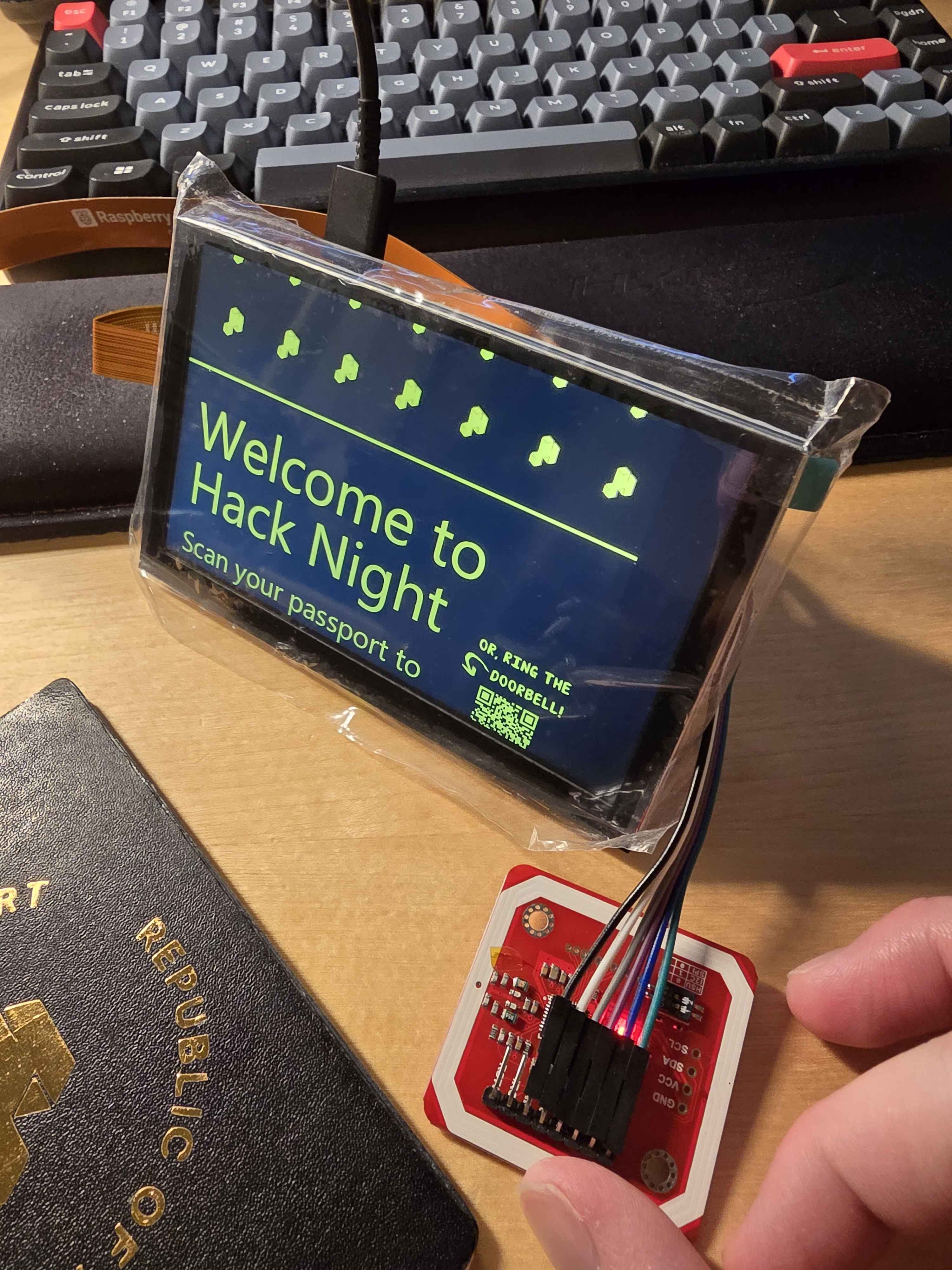
Prototype one
At the end of November, once all the parts had arrived from online marketplaces, I quickly connected together the loose parts on my desk and loaded up the same build from revision one. The visuals were messed up, as expected, but at least we had somewhere to start from!
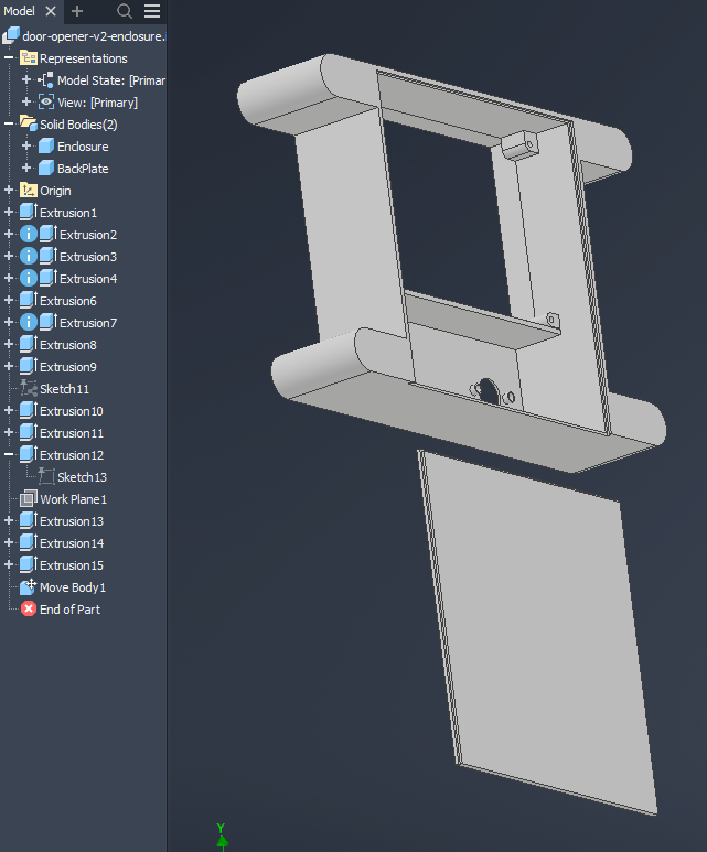
And since I had all the parts sitting in front of me, I took out the calipers and started to take measurements. After sketching out a rough idea of what I wanted, I opened Autodesk Inventor for the first time and made a rudimentary enclosure that would hold the parts together like a test bench:
And that wrapped up Fall 2025, and the rest of the semester was quite busy. After winter break, things picked back up again during the Spring 2026 semester.
What do we name the thing that pushes the ADA button? Some sort of ADA pusher?
Several things happened in parallel as we raced to get this project complete. We finally had the proper linear actuator that had the specifications we needed, shipped all the way from China. It needed 12V of power to operate, and we had an ESP32 board to interface via BLE and send signals to the linear actuator.
At first, I thought that I would only need one USB-PD trigger board and one step-down converter, to change the voltage from 12V to 5V for the ESP32. The trigger board would negotiate 12V from the power source and cleanly power everything.
Unfortunately, if you are familiar with the USB consortium, they actually made the 12V Power Delivery profile optional, which meant a lot of chargers flat-out do not support it. The justification was lack of use: phones usually topped up at around 9V, while laptops and tablets usually went up to 15V and 20V. Thus, the 9V profile was out of the question, even though it would’ve been perfect for our use case.
We couldn’t rely on specific chargers supporting it, because there was a chance that the charger we were using broke and the replacement wouldn’t have the optional profile. And if the charger didn’t support it, rather than risk frying the downstream device, the negotiation automatically shifted down to the next lower voltage profile, which was either 9V or 5V.
Thus, the new plan was to use two step-down converters and bring the 15V voltage negotiated by the trigger board down, to 12V and 5V, respectively.
After waiting a couple more days for all the parts to arrive, the first
prototype of ada-pusher also materialized on the dining table:
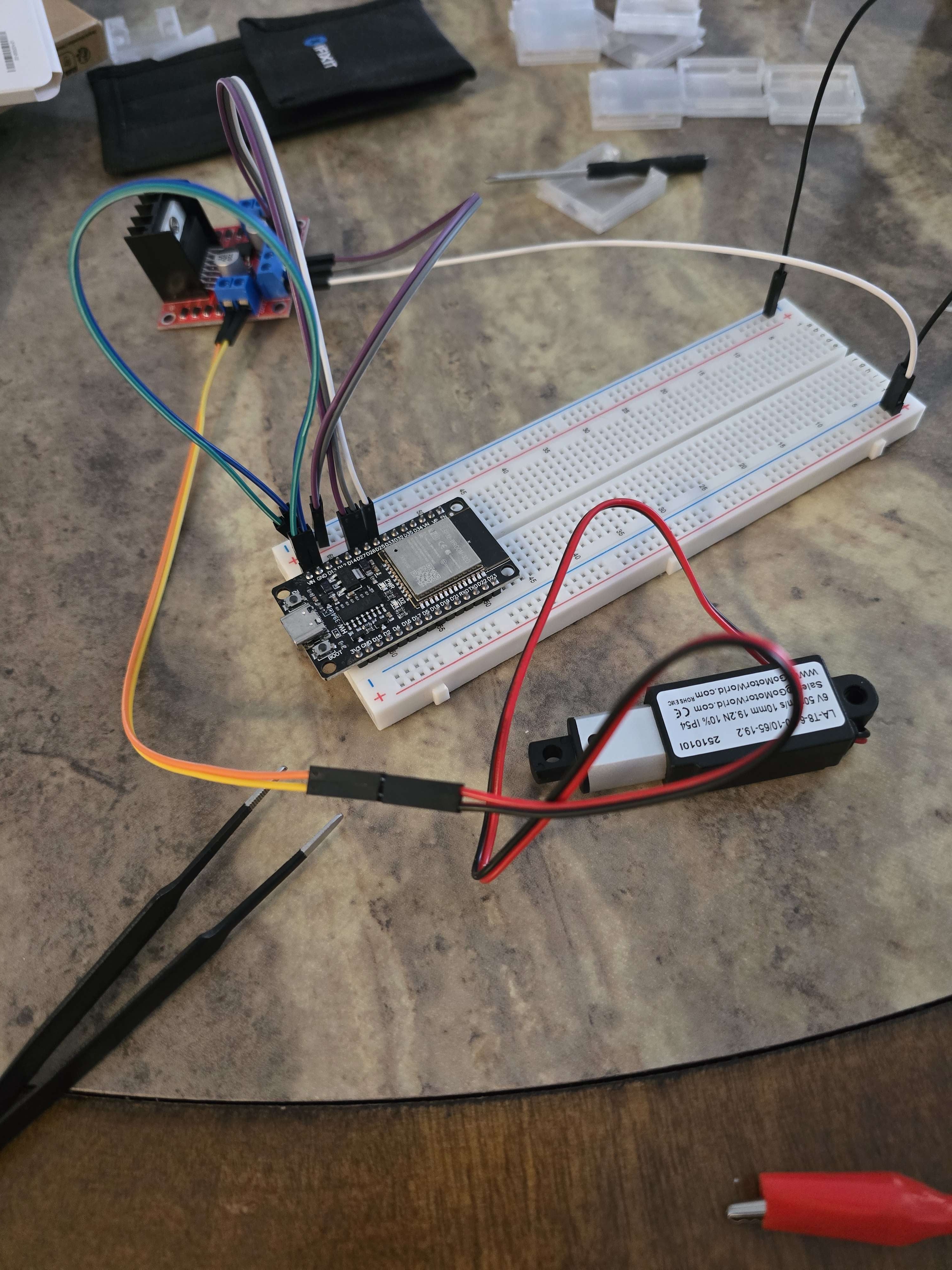
Through this test, we confirmed that the linear actuator module worked, and that the ESP32 board could properly send the signals when prompted.
Then came the topic of mounting the ada-pusher. We came up with several design
ideas, including utilizing the wall panel gaps just above the ada-pusher: